
- Availability: Нету в наличии
- Product Code: servo
- Product overview
- Reviews (0)
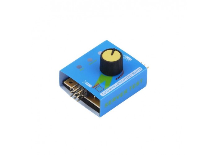
The Servo Tester is a compact, high-efficiency diagnostic tool engineered for real-time testing, calibration, and centering of up to three standard or micro servo mechanisms simultaneously. Designed for hardware developers, drone technicians, and RC hobbyists, this module provides instant feedback on electronic speed controllers (ESCs) and servo responsiveness across three distinct operational routines. Enclosed in a highly portable 35mm x 32mm footprint, it operates safely within a standard DC 4.8V to 6.0V power window, completely eliminating the need for a dedicated radio transmitter or receiver setup during bench diagnostics.
Features
Multi-Servo Parallel Testing Hub: Outfitted with a triple 3-pin output row, enabling the simultaneous connection and testing of up to three servos or ESC modules to compare tracking synchronization and speed variances.
Three-Position Manual Adjust Mode: Provides precision manual control via an integrated rotary potentiometer knob, allowing technicians to sweep the signal pulse width smoothly to evaluate structural travel limits, gear train binding, and overall resolution.
Instant Neutral Centering Calibration: Features a dedicated centering routine that instantly locks all connected servos into their exact median position (typically 1500 microseconds), streamlining mechanical linkage alignment during airframe or vehicle assembly.
Automated Cycle Endurance Subroutine: Includes an automated "Window Wiper" sweeps cycle that drives the servos continuously through their full articulation range to quickly detect intermittent signal losses, power brownouts, or mechanical gear fatigue.
Broad ESC Driver Compatibility: Acts as a standalone hardware pulse generator capable of mimicking receiver signals to drive and throttle-test Electronic Speed Controllers directly on the test bench without initializing complete radio link infrastructures.
Specifications
Brand: Standard RC Component Architecture
Model Name: 3-Channel Precision Bench Servo Tester & ESC Driver Module
Simultaneous Test Output Capacity: Up to 3 Independent Servo / ESC Signal Outputs
Primary Operating Input Voltage Window: DC 4.8 V – 6.0 V Regulated Input Range
Signal Output Interface Pins: Standard 3-Pin Header Matrix (Signal, Positive Power, Ground)
Physical Component Footprint: 35.0 mm × 32.0 mm × 24.0 mm
Physical Structural Net Mass: Ultra-Lightweight Bench-Diagnostic Framework
Operational Routines & Modes
Manual Mode: Manual sweep control using the onboard rotary potentiometer knob.
Neutral Mode: Automatic homing command to lock servos into their absolute center orientation.
Automatic Mode: Continuous automated full-range tracking loop for endurance and load stress evaluation.
Operational Instructions
Power Input Integration: Connect a regulated DC 4.8V to 6.0V power source (such as a 4-cell NiMH pack or a dedicated 5V BEC module output) directly into the tester's 3-pin input pins, paying strict attention to the pin polarity markings printed on the casing.
Servo Hardware Linkage: Insert your servo connectors straight into the triple output headers. Ensure that the ground wire (typically brown or black) and the signal line (typically orange or yellow) match the corresponding Ground (GND) and Signal (S) positions on the board layout.
Routine Selection Navigation: Press the tactile mode selection switch to toggle through the internal routines. The active setting will be visually confirmed by a localized indicator LED shifting between Manual, Neutral, and Automatic tracking positions.
Manual Sweep Calibration: Switch the device into Manual mode and rotate the integrated analog dial slowly from side to side. Monitor the mechanical travel profile of the connected servos to identify stuttering steps, loose gear play, or localized current binding.
Electronic Speed Controller Testing: To test an ESC, connect the speed controller's built-in BEC lead directly to the input headers to power the device, then route the throttle control wire back through an output channel to spin and test motor performance safely on the bench.
Notes Strict Voltage Protection Thresholds: This diagnostic component is strictly rated for an upper operating boundary of DC 6.0V. Never attach raw, unregulated high-voltage power leads (such as direct 2S or 3S LiPo battery lines) to the input rails, as exceeding the input voltage constraints will instantly fry the internal timing chips and permanently destroy connected low-voltage servos. High-Current Multi-Servo Safety: While the tester can output signal commands to three servos simultaneously, the total current draw of heavy-duty or high-torque digital servos under load can easily overwhelm small power supplies. Always ensure your primary 5V BEC source or bench power supply has sufficient amperage capacity to prevent voltage brownouts during multi-servo testing. Correct Pin Polarity Matching: Always cross-reference the servo wire color layout with the tester's interface markings before sending power to the circuit. Plugging a servo or input power cable into the headers backward can reverse the polarity matrix, damaging the internal microcontrollers or stripping out the delicate electronics inside your servo modules. Propeller Isolation During VTX/ESC Diagnostics: When utilizing the servo tester to check an Electronic Speed Controller connected to a drone or model motor, always remove all spinning propeller blades from the motor shafts first. Unexpected signal sweeps or initialization throttle spikes can spin the motor to full velocity instantly, posing a severe physical injury risk.
Package 1 x 3-Channel Precision Bench Servo Tester & ESC Pulse Generator Module